PSoC5LP Lab23: Building a UART‑Based Single‑Application Bootloader
Objective
Upon completion of this lab, you will be able to:
- Explain the architecture and flash memory layout of PSoC 5LP bootloader systems
- Design and implement Single-Application, Dual-Application, Launcher-Combination, Upgradeable Stack, and Dual-Application with Combination bootloader projects using PSoC Creator 4.4
- Evaluate the trade-offs among bootloader architectures in terms of update safety, flash utilization, and field upgradeability.
- Verify bootloader operation by transferring .cyacd firmware files via the PSoC Bootloader Host tool and observing application behavior on hardware.
Overview
A bootloader is a small program that runs immediately after a microcontroller resets. Its primary responsibility is to receive new firmware from an external host, write it into flash memory, verify its integrity, and transfer execution to the updated application. Bootloaders are essential in deployed embedded products that require firmware updates in the field without physical access to a programmer.
The PSoC 5LP (Programmable System-on-Chip 5 Low Power) from Infineon (formerly Cypress Semiconductor) provides a flexible bootloader framework through PSoC Creator. This framework offers pre-built Bootloader and Bootloadable components that handle the communication protocol, flash write operations, metadata management, and application validation automatically.
PSoC Creator supports five distinct bootloader architectures of increasing complexity:
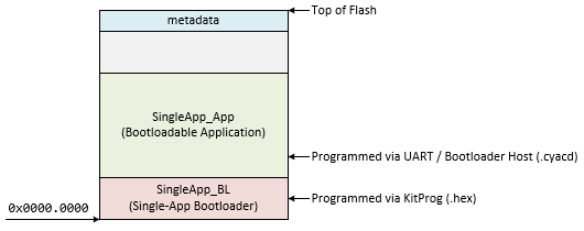
- Single-Application Bootloader — The simplest configuration. One bootloader project resides at the base of flash, and one bootloadable application occupies the remainder of the flash. The bootloader receives updates from a host and installs them in place of the application.
- Dual-Application Bootloader — Two application slots exist in flash. The bootloader always writes to the inactive slot, preserving the running application until the update is complete and verified. This prevents a failed update from bricking the device.
- Launcher and Combination Bootloader — A minimal bootloader (the Launcher) handles only application selection and jumping. Each application slot is a Combination project — it contains both a Bootloadable component (so it can be updated) and a Bootloader component (so it can update the other slot). This allows the update logic itself to be updated.
- Upgradeable Stack — Extends the Combination concept so that even the base bootloader can be replaced in the field. The entire firmware stack — bootloader and applications — is updatable without a programmer.
- Dual-Application Bootloader with Combination Project — Combines the safety of the dual-application scheme with the flexibility of the Combination project, providing both atomic slot-switching and updatable communication logic.
In all architectures, firmware update files use the .cyacd format and are transferred to the device using the PSoC Bootloader Host tool bundled with PSoC Creator.
A Single-Application Bootloader is the simplest PSoC 5LP bootloader configuration. It consists of two separate PSoC Creator projects that work together:
- Bootloader Project (Exp1_BL): A small program stored at the base of flash memory. It runs immediately after reset, waits for a firmware update command from a host computer via UART, and if received, writes the new application firmware into flash. If no command arrives within the timeout period, execution is transferred to the existing application.
- Bootloadable Project (Exp1_App): The actual application firmware stored above the Bootloader in flash. It is launched by the Bootloader after verification. In this experiment, it reads the state of the onboard switch SW1 and controls the onboard LED1 accordingly.
The firmware update file generated by the Bootloadable project is a .cyacd file, transferred to the device using the PSoC Bootloader Host tool via UART at 115200 baud.
Flash memory layout for this experiment:
PartA: Bootloader Project (SingleApp_BL)
Part A: Bootloader Project (SingleApp_BL)
Procedure
Creating a New Project
- Launch PSoC Creator.
- Go to File → Open → Project/Workspace and open your PSoC5LP workspace in the course folder.
- In the Workspace Explorer, right-click the Workspace and select Add → New Project....
- Select the correct PSoC 5LP device model number, and use the "Empty Schematic" template.
- Enter the project name: 23_Bootloader_SingleApp_BL.
- Click Finish.
Adding PSoC Creator Components
Open TopDesign.cysch and add the following components:
- UART:
- Navigate to the Communications catalog in the Component Catalog panel.
- Find and drag the
 UART onto the schematic.
- Bootloader:
- Navigate to the System catalog.
- Find and drag
 Bootloader onto the schematic.
- Logic '0':
- Navigate to the Digital → Logic catalog.
- Find and drag Logic Low '0' onto the schematic.
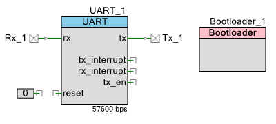
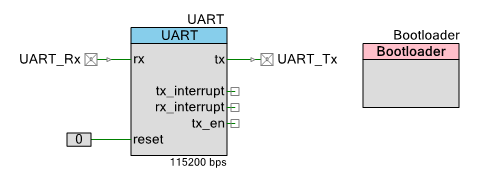
The TopDesign.cysch will be shown as below:
Configure the Components
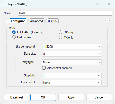
- Configure the UART (UART_1):
- Double-click UART_1 to open its configuration dialog.
- Set Name to UART_1.
- On the Configure tab, set:
- Mode: Full UART (TX + RX)
- Baud Rate: 115200
- Data Bits: 8
- Parity: None
- Stop Bits: 1
- Flow Control: None
- On the Advanced tab, set:
- RX Buffer Size: 64
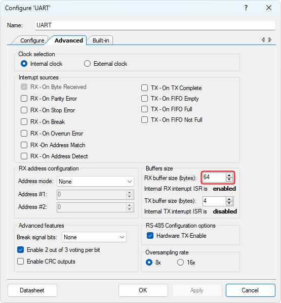
The PSoC 5LP Bootloader component requires a minimum RX buffer size of 64 bytes. Setting a smaller value will cause a build error.
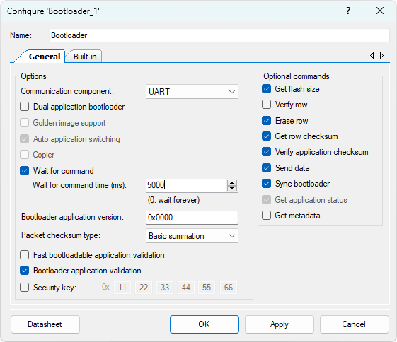
- Configure the Bootloader (Bootloader_1):
- Double-click Bootloader_1.
- Set the following parameters:
- Name: Bootloader
- Communication Component: UART
- Packet Checksum Type: Basic Summation
- Wait for Command (ms): 5000
- Enable Fast App Validation: Unchecked
- Configure the Digital Input Pin (Rx_1):
- Select the Rx_1 component.
- Rename the component to UART_Rx to indicate its role as the UART receive pin.
- Configure the Digital Input Pin (Tx_1):
- Select the Tx_1 component.
- Rename the component to UART_Tx to indicate its role as the UART transmit pin.
Wiring
Connect the Logic Low '0' output to the reset pin of the UART on the schematic. This holds the UART reset line inactive (deasserted) at all times, ensuring the UART operates normally during bootloader communication.
The new TopDesign.cysch file is shown below:
Pin Assignment
| Device | Port.Pin | Direction | Drive Mode |
|---|---|---|---|
Example Firmware C Code
main.c
#include "project.h"
#include <stdio.h>
#include <stdlib.h>
#include <stdint.h>
#include <stdbool.h>

int main(void)
{
    /* Start the Bootloader.
       Waits up to 5000 ms for a host command via UART.
       If no command is received within the timeout,
       it automatically jumps to the application.
       This function never returns. */
    Bootloader_Start();

    for(;;)
    {
        /* Never reached */
    }
}
Build the project: right-click 23_Bootloader_SingleApp_BL → Set as Active Project → Build → Build "23_Bootloader_SingleApp_BL". Confirm the build succeeds and note the .hex file path in the Build Output window.
Part B: Bootloadable Application Project (SingleApp_App)
Part B: Bootloadable Application Project (SingleApp_App)
Procedure
Creating a New Project
- Launch PSoC Creator.
- Go to File → Open → Project/Workspace and open your PSoC5LP workspace in the course folder.
- In the Workspace Explorer, right-click the Workspace and select Add → New Project....
- Select the correct PSoC 5LP device model number, and use the "Empty Schematic" template.
- Enter the project name: 23_Bootloader_SingleApp_App.
- Click Finish.
Adding PSoC Creator Components
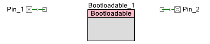
Open TopDesign.cysch and add the following components:
- Bootloadable:
- Navigate to the System catalog.
- Drag Bootloadable onto the schematic.
- Digital Input Pin (for SW1):
- Navigate to the Ports and Pins catalog.
- Drag a Digital Input Pin onto the schematic.
- Digital Output Pin (for LED1):
- From the Ports and Pins catalog.
- Drag a Digital Output Pin onto the schematic.
The TopDesign.cysch is shown below:
Configure the Components
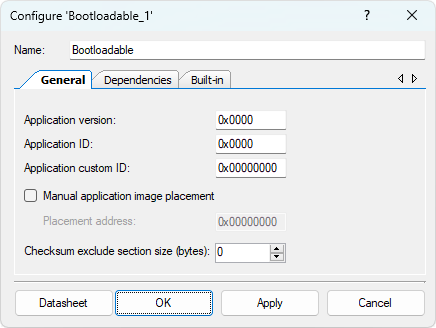
- Configure the Bootloadable (Bootloadable_1):
- Double-click Bootloadable_1.
- Set name to Bootloadable.
- On the General tab, set:
- Application version: 0x0000
- Application ID: 0x0000
- Application custom ID: 0x00000000
- Manual application image placement: Unchecked
-
On the Dependencies tab:
- Bootloader HEX file: Click Browse and navigate to the output folder of 23_Bootloader_SingleApp_BL, select 23_Bootloader_SingleApp_BL.hex.
- Bootloader ELF file: Click Browse and navigate to the same output folder, select 23_Bootloader_SingleApp_BL.elf.
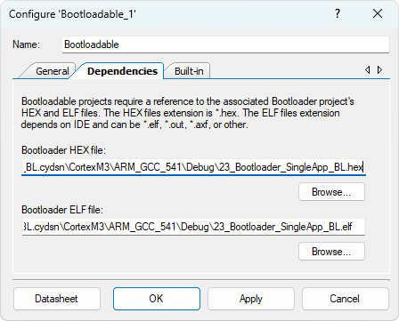
The Bootloader project (23_Bootloader_SingleApp_BL) must be built before the HEX and ELF files are available for browsing.
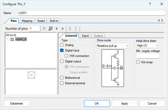
- Configure the Digital Input Pin (Pin_1):
- Double-click Pin_1.
- Set the following:
- Name: nSW1
- Type: Digital Input
- HW Connection: unchecked
- Drive Mode: Resistive Pull Up
- Initial Drive State: High (1)
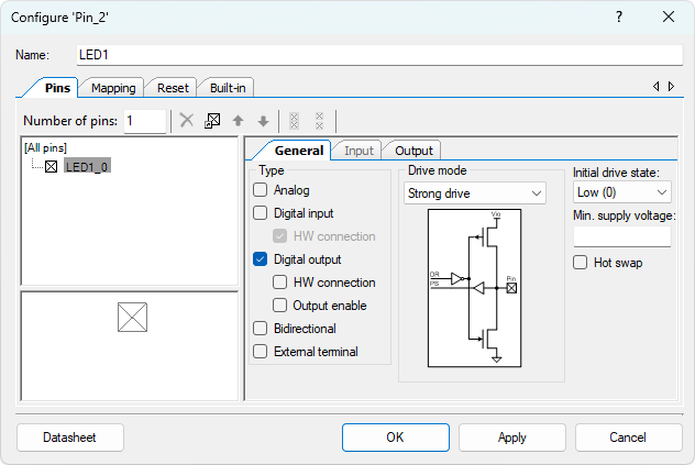
- Configure the Digital Output Pin (Pin_2):
- Double-click Pin_2.
- Set the following:
- Name: LED1
- Type: Digital Output
- HW Connection: Unchecked
- Drive Mode: Strong Drive
- Initial State:Low (0)
Pin Assignment
| Device | Port.Pin | Direction | Drive Mode |
|---|---|---|---|
Example Firmware C Code
main.c
#include "project.h"
#include <stdio.h>
#include <stdlib.h>
#include <stdint.h>
#include <stdbool.h>

int main(void)
{
    CyGlobalIntEnable; // Enable global interrupts

    for(;;) {
        // nSW1 is active-low:
        //   nSW1_Read() == 0 → button pressed
        //   nSW1_Read() == 1 → button released
        if (nSW1_Read() == 0) {
            LED1_Write(1); // Button pressed  → LED ON
        } else {
            LED1_Write(0); // Button released → LED OFF
        }
        CyDelay(20);
    }
}
Build the project: right-click 23_Bootloader_SingleApp_App → Set as Active Project → Build → Build "23_Bootloader_SingleApp_App". Confirm the build succeeds and note the .cyacd file path in the Build Output window.
Part C: Programming and Testing
Part C: Programming and Testing
Step 1 — Program the Bootloader via KitProg
- Connect the CY8CKIT-059 to the PC using the KitProg USB connector (the left-side USB port labeled KitProg).
- In PSoC Creator, right-click Exp1_BL → Program.
- Wait for programming to complete. The device now runs the Bootloader and immediately begins the 5-second wait window.
Step 2 — Transfer the Application via Bootloader Host
- Press the Reset button on the CY8CKIT-059. The Bootloader starts and opens its 5-second UART command window.
- Open PSoC Bootloader Host: in PSoC Creator, go to Tools → Bootloader Host.
- Configure the tool:
Field Value File Browse to 23_Bootloader_SingleApp_App.cyacd.cyacd Protocol UART COM Port CY8CKIT-059 UART COM port (check Windows Device Manager → Ports) Baud Rate 115200 bps - Click the Program within the 5-second timeout window.
Wait for the transfer to complete. The device resets automatically and launches Exp1_App.
Step 3 — Verify Operation
ActionExpected ResultPress and hold SW1LED1 turns ONRelease SW1LED1 turns OFFPress Reset buttonLED goes OFF; 5-second pause (Bootloader waiting); LED behavior resumes