Lesson 13: Bootloader
13.1 Bootloader Fundamentals
Bootloader Fundamentals
This module introduces the fundamental concepts of bootloaders in embedded systems, focusing on the PSoC 5LP architecture. Students will learn how firmware updates are performed, how bootloaders differ from traditional programming methods, and how the overall system is structured.
Table of Contents
- 1. What is a Bootloader?
- 2. Bootloader vs ISP (JTAG / SWD)
- 3. Host / Target Architecture
- 4. Bootloadable Application Concept
- 5. Flash Memory Overview
- 6. Terminology & System Model
1. What is a Bootloader?
A bootloader is a small program stored in the microcontroller’s flash memory that enables firmware updates without requiring physical access to hardware programming interfaces.
Instead of using JTAG or SWD, the bootloader supports firmware updates via UART, I2C, USB, or SPI.
Key Features
- Runs immediately after reset
- Receives firmware from external host
- Programs flash memory
- Transfers control to the application
2. Bootloader vs ISP (JTAG / SWD)
ISP (JTAG / SWD)
- Requires physical connection
- Used in development and manufacturing
- Provides full debugging capability
Bootloader
- No physical access required
- Used for field firmware updates
- Limited debugging capability
| Feature | Bootloader | ISP |
|---|---|---|
| Access | Remote | Physical |
| Use Case | Field update | Development |
| Speed | Medium | Fast |
3. Host / Target Architecture
A bootloader system consists of two main parts:
- Host — sends firmware data
- Target — receives and programs firmware
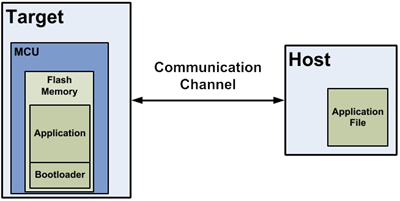
Figure 1: Bootloader System
Flow
- The host sends firmware
- Bootloader receives data
- Flash is programmed
- Application is executed
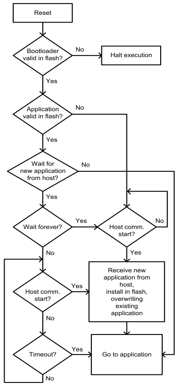
Figure 2: Bootloader Function Flow
4. Bootloadable Application Concept
A bootloadable application is the firmware that runs on the MCU and can be updated by the bootloader.
- Stored in flash memory
- Validated before execution
- Updated via bootloader
Execution Flow
- Bootloader starts
- Application is validated
- If valid → run application
- If invalid → stay in bootloader
5. Flash Memory Overview
PSoC 5LP flash memory is organized into rows, the smallest programmable units.
- 1 row = 256 bytes (main flash)
- + ECC for error correction
Characteristics
- Write per row
- Erase required before writing
- Slower than RAM
6. Terminology & System Model
Key Terms
- Bootloading — firmware update process
- Host — data source
- Target — device being updated
- Bootloader — update manager
- Bootloadable — application
System Model
- Host prepares firmware
- Data sent via the communication interface
- Bootloader receives packets
- Flash is updated row-by-row
- Application is validated and executed
Summary
This module establishes the foundational understanding of bootloader systems. Students should now understand the role of bootloaders, how firmware updates are performed, and how the system is structured before moving into architecture and implementation.
13.2 PSoC Bootloader Architecture
PSoC Bootloader Architecture
This module introduces the architecture of the PSoC bootloader system. Students will learn the difference between the Bootloader and Bootloadable components, understand the available project types in PSoC Creator, and study how flash memory is partitioned to support safe firmware updates.
Table of Contents
- 1. Bootloader Component vs Bootloadable Component
- 2. Project Types in PSoC Bootloader System
- 3. Single-Application vs Dual-Application Bootloader
- 4. Metadata Structure and Application Validation
- 5. Bootloader Memory Layout (Flash Partitioning)
1. Bootloader Component vs Bootloadable Component
In PSoC Creator, the bootloading system is built around two key components:
- Bootloader Component
- Bootloadable Component
Bootloader Component
Bootloader Component
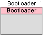
The Bootloader component is responsible for managing the firmware update process. It communicates with the host, receives firmware data, programs flash memory, and determines whether the application is valid before execution.
- Handles communication with the host
- Processes bootloader commands
- Programs flash memory row-by-row
- Validates the application
- Transfers control to the application
BootloadableComponent
Bootloadable Component
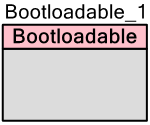
The Bootloadable component represents the main user application that can be updated by the bootloader. It is linked to a specific bootloader project during build time.
- Contains user application logic
- Can be updated through the bootloader
- Includes metadata for validation
- Does not directly write to flash
Comparison
| Feature | Bootloader | Bootloadable |
|---|---|---|
| Main Purpose | Firmware update management | User application execution |
| Runs First After Reset | Yes | No |
| Programs Flash | Yes | No |
| Communicates with Host | Yes | Normally No |
2. Project Types in PSoC Bootloader System
PSoC Creator automatically determines the project type based on the components placed in the design.
Normal Application
Normal Application
- No bootloader-related components
- Standard firmware project
- Programmed using JTAG or SWD
- No field update capability
Bootloader Project
Bootloader Project
- Contains a Bootloader component and a communication component
- Receives firmware data from the host
- Writes data into flash memory
- Launches the application after validation
Bootloadable Project
Bootloadable Project
- Contains a Bootloadable component
- Represents the application that will be downloaded into Flash
- Depends on a matching bootloader project
Combination Project
Combination Project
- Contains Bootloader + Bootloadable + communication component
- Can run as an application and also update another application
- Used in advanced multi-application systems
Launcher Project
Launcher Project
- Contains a Bootloader component without a communication component
- The main job is to verify and launch applications
- Often used in combination-based architectures
Quick Summary Table
| Project Type | Main Function |
|---|---|
| Normal Application | Regular firmware only |
| Bootloader | Receives and installs firmware updates |
| Bootloadable | An application that can be updated |
| Combination | Application + updater in one project |
| Launcher | Selects and launches applications |
3. Single-Application vs Dual-Application Bootloader
Single-Application Bootloader
Single-Application Bootloader
A single-application bootloader supports only one bootloadable application in flash memory.
- Simpler design
- Lower flash usage
- Only one application image is stored
However, if the update process fails and the application becomes corrupted, the system may not be able to run the application until a successful recovery update is performed.
Dual-Application Bootloader
Dual-Application Bootloader
A dual-application bootloader supports two application slots in flash memory.
- Application 1 and Application 2 are stored separately
- The bootloader can select which application to run
- Provides better recovery and fail-safe behavior
Advantages of Dual-Application Design
- One application can remain valid while the other is updated
- Supports fallback if the new firmware is invalid
- Improves reliability in field update systems
Trade-Off
Because flash memory must be divided between two applications, each application gets less available space compared to a single-application design.
4. Metadata Structure and Application Validation
Each bootloadable application includes metadata stored in flash memory. This metadata is used by the bootloader to determine whether the application is valid and executable.
Typical Metadata Information
- Application start address
- Application length
- Checksum or validation value
- Active application flag
- Additional control information
Application Validation Process
- Bootloader reads metadata from flash
- Bootloader checks stored validation information
- The bootloader calculates the checksum of the application image
- Bootloader compares the calculated result with the metadata
- If valid, control is transferred to the application
- If invalid, the bootloader remains active
This validation step is critical because it prevents the system from jumping to corrupted or incomplete firmware.
Why Metadata Matters
- Improves system reliability
- Supports safe firmware switching
- Allows the bootloader to detect update failures
- Enables application selection in dual-app systems
5. Bootloader Memory Layout (Flash Partitioning)
To support bootloading, the flash memory must be partitioned into separate regions. Each region has a specific purpose.
Typical Flash Regions
- Bootloader Region — stores bootloader firmware
- Application Region — stores bootloadable application
- Metadata Region — stores validation and control information
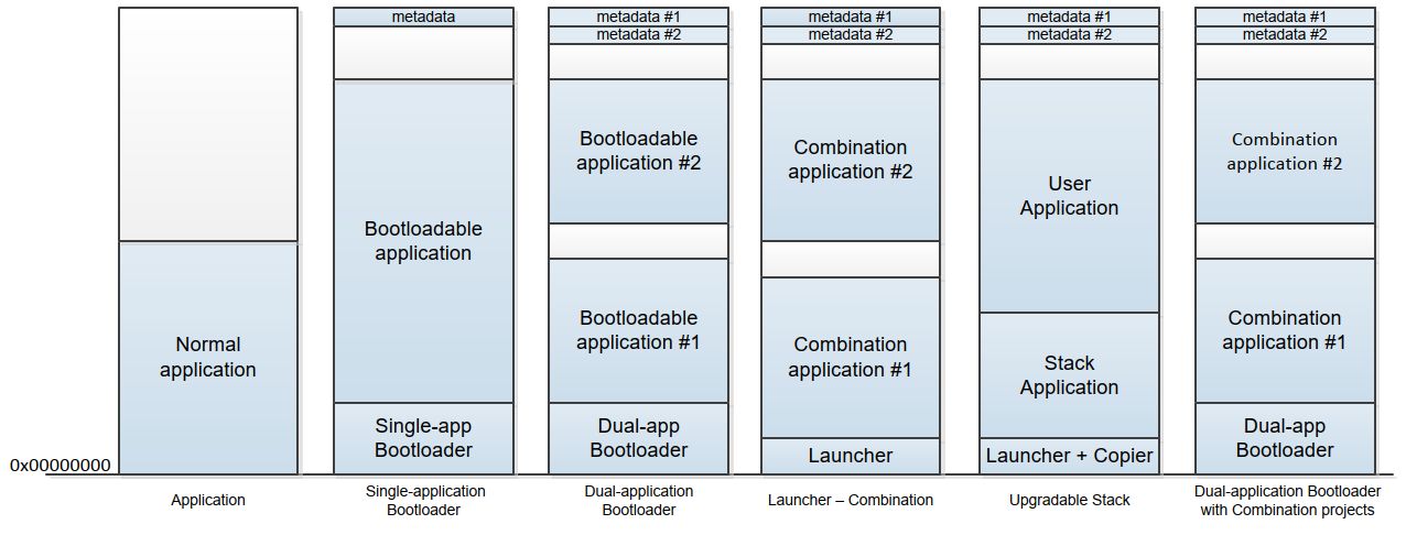
Figure: Flash Memory Usage
Single-Application Layout
- Bootloader area
- Application area
- Metadata area
Dual-Application Layout
- Bootloader area
- Application 1 area
- Application 2 area
- Metadata 1 area
- Metadata 2 area
Design Considerations
- The bootloader region must be protected from overwriting
- Application regions should align with flash row boundaries
- Enough space must be reserved for metadata
- Application size must fit the available partition
A correct memory layout is one of the most important parts of a successful bootloader system. Poor partitioning can make firmware updates unreliable or even impossible.
Summary
This module introduced the architecture of the PSoC bootloader system. Students should now understand the roles of the Bootloader and Bootloadable components, the different project types available in PSoC Creator, and how metadata and flash partitioning support safe firmware updates.
With this architectural foundation, the next module can focus on how the bootloader actually executes after reset, validates the application, and interacts with the host during the update process.
13.3 Bootloader Execution Flow
Bootloader Execution Flow
This module explains how the PSoC bootloader runs after reset, how it validates the application, how the communication window works, and how the bootloader interacts with the host during firmware updates. This execution flow is one of the most important parts of understanding how a bootloader system works in practice.
Table of Contents
- 1. Reset to Bootloader Execution Sequence
- 2. Application Validation Process
- 3. Timeout and Communication Window
- 4. Bootload Process Flow (Host ↔ Target)
- 5. Bootloader Decision Logic
- 6. Complete Flow Summary
1. Reset to Bootloader Execution Sequence
In a PSoC bootloader system, the bootloader is typically the first code that executes after a device reset. This allows the system to check the firmware status and determine whether to run the existing application or remain in bootloader mode for an update. :contentReference[oaicite:0]{index=0}
Typical Reset Sources
- Power-on reset
- External reset
- Watchdog reset
- Software reset
Execution Sequence
- The device resets
- The bootloader starts execution from flash
- The bootloader initializes required hardware resources
- The bootloader checks whether the application is valid
- The bootloader opens a communication window
- The bootloader decides whether to jump to the application or stay in bootloader mode
This startup sequence is important because it gives the bootloader full control before any application code runs.
2. Application Validation Process
Before the bootloader transfers control to the application, it must confirm that the application image stored in flash is valid. This protects the system from jumping to corrupted or incomplete firmware. :contentReference[oaicite:1]{index=1}
What the Bootloader Checks
- Application metadata exists
- Application length and location are correct
- Checksum or validation value matches
- Application image is complete and executable
Validation Flow
- The bootloader reads metadata from flash
- The bootloader calculates the checksum of the application image
- The bootloader compares the calculated result with the stored metadata
- If the values match, the application is considered valid
- If the values do not match, the application is considered invalid
Why Validation Is Necessary
- Prevents execution of corrupted firmware
- Supports safe firmware update mechanisms
- Improves system reliability after interrupted updates
- Enables fallback behavior in advanced designs
3. Timeout and Communication Window
After a reset, the bootloader usually waits for a short period to see whether a host wants to start a firmware update. This period is called the communication window. If no valid communication is detected before the timeout expires, the bootloader normally jumps to the application.
Communication Window Purpose
- Allows the host to begin a bootload session
- Prevents unnecessary delay during normal startup
- Balances update flexibility and boot speed
Possible Timeout Behaviors
- Short timeout for fast startup
- Longer timeout for easier maintenance
- Infinite wait mode in customized bootloader designs
Engineering Trade-Off
| Timeout Setting | Effect |
|---|---|
| Short | Faster startup, but easier to miss an update request |
| Long | More update-friendly, but increases boot delay |
| Infinite | Always available for update, but the application will not start automatically |
In some systems, the bootloader can also be customized to wait for a hardware trigger, such as a button press, before entering update mode. :contentReference[oaicite:3]{index=3}
4. Bootload Process Flow (Host ↔ Target)
The bootload process is a structured interaction between the host and the target device. The host controls the update process, and the bootloader responds to commands, writes firmware data to flash, and returns status information.
Host Responsibilities
- Load the firmware file
- Split the firmware into data packets or rows
- Send commands to the target
- Monitor acknowledgments and error codes
- Complete the session and exit bootloader mode
Target Responsibilities
- Receive host commands
- Parse communication packets
- Program flash memory row-by-row
- Verify flash operations
- Return status responses to the host
Typical Bootload Flow
- The host sends a command to enter bootloader mode
- Bootloader acknowledges and reports device information
- The host sends firmware data packets
- Bootloader writes each firmware row into flash
- Bootloader verifies programming result
- Host continues until all rows are transferred
- Host sends exit command
- Bootloader resets or jumps to the application
Important Characteristics
- The host initiates all communication
- The bootloader does not start communication by itself
- Flash programming is performed one row at a time
- Each transaction must be verified for reliability
5. Bootloader Decision Logic
The bootloader must decide after reset based on application validity, host activity, and timeout status. This decision logic determines the behavior of the entire firmware update system.
Possible Decisions
5.1 Jump to Application
The bootloader jumps to the application when:
- The application is valid
- No host communication is detected during the communication window
- No forced bootloader condition is active
This is the normal operating path for a device that already has a valid firmware image.
5.2 Stay in Bootloader
The bootloader stays active when:
- The application is invalid
- The application is missing
- A recovery or maintenance mode is required
- The design is configured for infinite wait mode
This behavior allows the system to recover from failed updates or corrupted firmware.
5.3 Receive Update
The bootloader enters update mode when:
- The host starts communication within the timeout window
- A valid bootload command is received
Once in update mode, the bootloader remains engaged in the command-response process until the host completes the update or the session ends.
6. Complete Flow Summary
The complete execution flow of a bootloader can be summarized as follows:
- The device resets
- The bootloader starts running
- The bootloader validates the application
- The bootloader opens a communication window
- The bootloader checks for host activity
- If the application is valid and no host request is detected, jump to the application
- If the application is invalid, remain in bootloader mode
- If the host requests an update, start the bootload process
- After the update is complete, validate the new application
- Transfer control to the application
Conceptual Decision Model
| Condition | Bootloader Action |
|---|---|
| Application valid + no host request | Jump to application |
| Application invalid | Stay in the bootloader |
| Host request detected | Receive update |
Summary
This module explained how the bootloader behaves after reset, how it validates the firmware image, how the communication window works, and how the target interacts with the host during a firmware update session.
Students should now understand that the bootloader is not just a communication tool. It is a decision-making control layer that determines whether the system will run the application, wait for recovery, or enter firmware update mode.
With this execution-flow foundation, the next module can move into communication interfaces and protocol details, including UART, I2C, SPI, and USB-based bootloader operation.
13.4 Communication Interfaces & Protocol
Module 4 — Communication Interfaces & Protocol
This module introduces the communication interfaces used in PSoC bootloader systems and explains the underlying communication protocol. Students will learn how different interfaces compare in terms of performance and complexity, and how data is transferred between the host and the target using a structured, packet-based protocol.
Table of Contents
- 1. Supported Communication Interfaces
- 2. UART Interface
- 3. I2C Interface
- 4. SPI Interface
- 5. USB Interface
- 6. Interface Comparison
- 7. Packet Structure
- 8. Command / Response Model
- 9. Reliability Considerations
1. Supported Communication Interfaces
PSoC 5LP bootloader supports multiple communication interfaces. The choice of interface depends on system requirements such as speed, hardware availability, and deployment environment.
- UART
- I2C
- SPI
- USB
All interfaces use the same bootloader protocol, meaning that only the physical transport layer changes while the command structure remains consistent.
2. UART Interface
Overview
- Asynchronous serial communication
- Uses TX and RX signals
- No clock line required
Advantages
- Simple to implement
- Low hardware cost
- Easy PC integration using USB-to-UART adapters
Disadvantages
- Lower speed compared to USB or SPI
- Sensitive to baud rate mismatch
Typical Use
- Development and debugging
- PC-based firmware update
3. I2C Interface
Overview
- Synchronous communication
- Uses SDA (data) and SCL (clock)
- Master-slave architecture
Advantages
- Supports multiple devices on one bus
- Good for embedded-to-embedded systems
Disadvantages
- Requires pull-up resistors
- More complex protocol handling
- Susceptible to NAK during flash operations
Typical Use
- Embedded host updating target MCU
- Multi-device systems
4. SPI Interface
Overview
- Synchronous high-speed communication
- Uses MOSI, MISO, SCLK, and SS signals
Advantages
- Higher throughput than UART and I2C
- Deterministic timing
Disadvantages
- More pins required
- No built-in addressing
Typical Use
- High-speed embedded systems
- Board-to-board communication
5. USB Interface
Overview
- High-speed communication with PC
- Supports USB HID or CDC class
Advantages
- Highest throughput
- Direct PC connection
- No external converter required
Disadvantages
- More complex firmware design
- Requires USB-capable hardware
Typical Use
- Consumer devices
- Professional firmware update tools
6. Interface Comparison
| Interface | Throughput | Complexity | Reliability | Typical Use |
|---|---|---|---|---|
| UART | Low–Medium | Low | Medium | PC update |
| I2C | Low | Medium | High (with retry) | Embedded systems |
| SPI | High | Medium | High | High-speed systems |
| USB | Very High | High | High | PC interface |
7. Packet Structure
All communication between the host and the bootloader is performed using structured packets. This ensures reliable data transfer regardless of the physical interface.
Typical Packet Fields
- Start Byte — indicates start of packet
- Command Code — defines the operation
- Data Length — size of payload
- Data Payload — firmware or control data
- Checksum — ensures data integrity
- End Byte — marks the end of the packet
Each packet must be validated before processing to prevent corrupted data from being written to flash memory.
8. Command / Response Model
The bootloader communication follows a strict command-response model:
- The host acts as the master
- The bootloader acts as the responder
Communication Flow
- The host sends a command
- Bootloader processes the command
- Bootloader sends a response
Common Commands
- Enter Bootloader
- Get Device Information
- Program Row
- Verify Row
- Exit Bootloader
Response Types
- ACK (success)
- Error code
- Data response
The host always controls the sequence of operations. The bootloader never initiates communication on its own.
9. Reliability Considerations
Reliable communication is essential for successful firmware updates.
Key Techniques
- Checksum validation for each packet
- Retry mechanism for failed communication
- Timeout handling to detect errors
- Verification after flash write
Example: I2C NAK Behavior
During flash write operations, the bootloader may temporarily be unable to respond, causing a NAK. The host must detect this condition and retry the transmission.
Best Practices
- Always verify written data
- Implement retry logic in the host
- Avoid overly aggressive timing
- Test under worst-case conditions
Summary
This module introduced the communication interfaces supported by the PSoC bootloader and explained how data is transferred using a standardized protocol.
Students should now understand how different interfaces compare and how packet-based communication enables reliable firmware updates across all transport layers.
The next module will focus on implementing real bootloader systems using UART and I2C, including PSoC Creator configuration and debugging techniques.
13.5 UART and I2C Bootloader Implementation
Module 5 — UART and I2C Bootloader Implementation
This module focuses on the practical implementation of bootloader systems using UART and I2C in PSoC 5LP. Students will learn the architecture of both implementations, how to configure the required components in PSoC Creator, how the host interacts with the target during firmware updates, and the engineering issues to consider for reliable operation.
Table of Contents
- 1. Implementation Overview
- 2. UART Bootloader Architecture
- 3. UART Bootloader Configuration in PSoC Creator
- 4. Bootloader_Start() Behavior
- 5. UART Host Tool Interaction
- 6. Debugging UART Bootloader
- 7. I2C Bootloader Architecture
- 8. I2C Master / Slave Interaction
- 9. Embedded Host Design
- 10. Electrical Considerations
- 11. Reliability Issues (NAK and Retry)
- 12. UART vs I2C Implementation Summary
1. Implementation Overview
In PSoC 5LP, UART and I2C are two common communication interfaces for bootloader-based firmware update systems.
- UART bootloader is usually used when a PC or a USB-to-UART bridge acts as the host.
- I2C bootloader is usually used when another embedded controller acts as the host.
Although both implementations use the same bootloader concept, their system architectures, hardware requirements, and reliability concerns differ. Understanding both approaches helps students choose the correct design for a real embedded system.
2. UART Bootloader Architecture
The UART bootloader is one of the simplest and most widely used bootloader implementations. It is especially suitable for lab development, debugging, and PC-based firmware updates.
System Architecture
- Host — PC or external system sending the firmware image
- UART Interface — TX/RX communication channel
- Bootloader — receives commands and programs flash memory
- Bootloadable Application — the firmware image that will be executed after update
Basic UART Update Flow
- The host opens a UART connection to the target
- The bootloader receives bootload commands
- The host sends firmware rows to the target
- The bootloader writes the rows into flash memory
- The bootloader verifies the firmware and transfers execution to the application
Because a UART is simple and easy to connect to a PC, it is often the first interface used when teaching bootloader design.
3. UART Bootloader Configuration in PSoC Creator
To build a UART bootloader project in PSoC Creator, students typically configure two main components:
- Bootloader Component
- UART Component
3.1 Bootloader Component Configuration
- Add the Bootloader component to the TopDesign schematic
- Open the Bootloader configuration dialog
- Select UART as the communication component
- Use the default bootloader settings unless a custom design is required
3.2 UART Component Configuration
- Add the UART component to the design
- Set the UART mode to Full UART
- Assign TX and RX pins
- Configure the baud rate and communication format
Typical Engineering Notes
- Ensure the host and target use the same baud rate
- Verify TX and RX are cross-connected correctly
- Use the correct I/O voltage level when connecting to an external USB-to-UART adapter
4. Bootloader_Start() Behavior
The function Bootloader_Start() is the core API for starting bootloader operations.
Main Characteristics
- Initializes the bootloader communication process
- Waits for host commands
- Processes firmware update commands
- Programs flash memory as needed
- Ends with a software reset or application handoff
Important Design Note
Once Bootloader_Start() is called, the function normally does not return in the usual application sense. The bootloader manages the full update flow and then resets or transfers control when finished.
Instructional Caution
- Do not assume code after Bootloader_Start() will always execute
- Keep the bootloader flow simple and deterministic
- Avoid adding unnecessary logic after the bootloader start call
5. UART Host Tool Interaction
A UART bootloader requires a host application to send the firmware image to the target. In lab environments, this host is commonly a PC running a bootloader host tool.
Typical Host Responsibilities
- Open the serial port
- Load the bootloadable firmware file
- Send bootloader commands in sequence
- Transmit firmware rows
- Receive status and error responses
- Complete the update session
Typical UART Bootload Session
- Connect the target through UART
- Select the correct COM port
- Load the firmware file
- Start the bootload session
- Wait for the bootloader acknowledgment
- Program all required flash rows
- Exit the bootloader and allow the application to run
Lab Reminder
- Wrong COM port selection will prevent communication
- A wrong baud rate will cause corrupted communication
- A wrong firmware file or a mismatched bootloader/bootloadable pair may cause a validation failure
6. Debugging UART Bootloader
UART bootloader debugging is usually easier than debugging other interfaces, but several common problems still occur in practice.
Common Problems
- No response from the target
- Wrong baud rate
- TX/RX wiring reversed
- Target not actually entering bootloader mode
- Bootloadable image does not match the bootloader project
Recommended Debugging Procedure
- Verify power and ground
- Verify TX/RX connection
- Check the baud rate configuration on both the host and the target
- Confirm the bootloader starts after a reset
- Test communication with a serial terminal when needed
- Verify the correct firmware file is being used
Good Practice
- Keep the bootloader design minimal
- Use indicators such as LED status when helpful
- Test normal update and failure cases separately
7. I2C Bootloader Architecture
The I2C bootloader is commonly used in embedded systems where another MCU performs the firmware update. Instead of a PC host, the bootloader target is controlled by an embedded master.
System Architecture
- Embedded Host — another MCU acting as an I2C master
- I2C Bus — SDA and SCL signals
- PSoC 5LP Target — running the I2C bootloader as slave
- Flash Memory — stores the new firmware image
Main Characteristics
- The host always initiates communication
- The target bootloader acts as an I2C slave
- Firmware is transferred in packets and programmed row-by-row
This design is useful in closed systems where one controller manages the update of another controller.
8. I2C Master / Slave Interaction
I2C bootloader communication follows the standard master / slave communication model.
Master (Embedded Host)
- Generates the clock
- Starts all transactions
- Sends commands and firmware data
- Handles retries and timing control
Slave (Bootloader Target)
- Listens for its slave address
- Receives bootloader commands
- Returns status or data
- Programs flash memory when commanded
Typical I2C Transaction Flow
- The master sends a START condition
- The master sends the slave address
- The bootloader acknowledges the address
- The master sends a command or data bytes
- The bootloader responds with ACK, NAK, or status data
- The master sends a STOP condition
Because the host controls every transaction, the embedded host firmware must be carefully designed.
9. Embedded Host Design
An embedded host is a microcontroller or processor that performs the host role instead of a PC. This embedded host must handle the entire firmware update session.
Main Embedded Host Tasks
- Store or access the firmware image
- Initialize the I2C master interface
- Send bootloader commands in the correct order
- Break firmware into properly sized rows or packets
- Retry failed communication when necessary
- Verify update completion
Typical Embedded Host Sequence
- Initialize I2C hardware
- Enter bootloader communication mode
- Read the firmware image source
- Send firmware rows one at a time
- Check acknowledgment after each transaction
- Exit the bootloader after programming completes
Design Challenges
- Error handling must be robust
- Timeout behavior must be clearly defined
- Firmware storage management may require external memory
10. Electrical Considerations
Unlike UART, I2C depends heavily on proper electrical design. A bootloader may fail even if the firmware is correct when the bus hardware is not designed properly.
10.1 Pull-up Resistors
I2C requires pull-up resistors on both SDA and SCL.
- Pull-up resistors restore the line to logic HIGH
- I2C devices typically pull the line LOW only
- Without pull-ups, the bus cannot operate correctly
10.2 Open-Drain Configuration
I2C pins must be configured for open-drain operation.
- This prevents direct bus contention
- It allows multiple devices to share the same bus safely
- Push-pull configuration is incorrect for standard I2C signaling
10.3 Additional Practical Notes
- Keep the bus traces reasonably short
- Reduce excessive capacitance on the bus
- Ensure a common ground between the host and the target
11. Reliability Issues (NAK and Retry)
I2C bootloader systems must be designed to handle communication interruptions, especially during flash write operations.
11.1 NAK Behavior
During flash programming, the target bootloader may not always be ready to respond immediately. This can result in a NAK.
Typical Causes
- Flash row write delay
- Internal timing changes during flash operation
- Temporary unavailability of the bootloader response path
11.2 Retry Strategy
The embedded host must implement retry logic.
- Detect NAK or timeout
- Wait for a short delay
- Resend the command
- Limit the maximum number of retries
11.3 Reliability Best Practices
- Always verify successful write operations
- Use checksums and status checking
- Implement timeout recovery
- Test the design under slow and worst-case conditions
12. UART vs I2C Implementation Summary
| Feature | UART Bootloader | I2C Bootloader |
|---|---|---|
| Typical Host | PC or USB-to-UART bridge | Embedded MCU |
| Hardware Simplicity | High | Medium |
| Electrical Sensitivity | Lower | Higher |
| Best Use Case | Development and PC update | Embedded system update |
| Main Reliability Concern | Baud rate/wiring mismatch | NAK/retry/bus timing |
Summary
This module introduced the practical implementation of UART and I2C bootloader systems in PSoC 5LP. Students should now understand how both implementations are structured, how they are configured in PSoC Creator, how the host interacts with the target, and what engineering issues affect reliability.
The UART bootloader is usually the simpler entry point for PC-based firmware update, while the I2C bootloader is more suitable for embedded host systems that require controller-to-controller update capability.
With this implementation knowledge, students are ready to move on to advanced topics such as bootloadable application design, dual-application systems, metadata handling, and fail-safe update strategies.